
Electrothermal Capacitors
Description
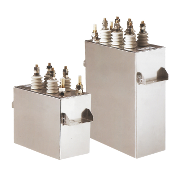
Electrothermal capacitors are used if you have induction heating furnaces in your production. With their help, the power factor of electrothermal installations with a frequency of 0.5–30 kHz is increased. Manufactured in a climatic version for temperate climates and for indoor placement. The production of this type of capacitors is at the development stage.
Characteristics
Technical Specifications :
| Output | Up to 8‚400 kVAr | Voltage | Up to 4‚000 Volts AC |
|---|---|---|---|
| Frequency | Up to 20‚000 Hz | Tappings | Tapped / Untapped |
| Phase | Single Phase | Cooling | Water Cooled |
| Mounting | Horizontal / Vertical | Casing | Aluminum / Brass |
| Case Design | Isolated (Dead) / Live Case | Protection | Thermal & Over Pressure Cut–off |
| Standards | IEC : 60110–1‚ EN : 60110–1/ 2‚ ISS : 9251 |
Capacitors can be supplied with either of the following configurations depending on the applications & customers requirements.
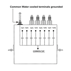
Configuration 1
Single cooled–live case design‚ with sub–sections. (one terminal connected to casing)
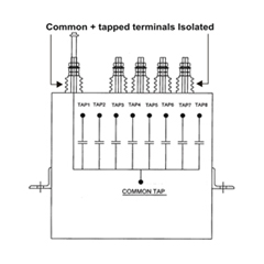
Configuration 2
Single cooled–isolated / dead case design‚ with sub–sections. (all terminals isolated)
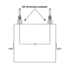
Configuration 3
Double cooled–isolated / dead case design‚ without sub–sections. (all terminals isolated)
The performance and operating life of water–cooled capacitors are determined by effective cooling conditions. As water–cooling plays a vital role‚ all related parameters such as water quality‚ required minimum & maximum water flow‚ water pressure‚ in–let and out–let water temperature‚ assume critical importance and must be closely monitored to achieve desired results. (Refer relevant charts & recommendations).
- Rated water flow should be minimum 5 L/min. Maximum pressure drop of 140 m bars.
- In–let water temperature should not exceed 35°C & out–let water temperature should be limited to maximum 45–50°C. Ideally‚ the difference between the in–let & out–let water temperature should be around 10°C.
- Pressure drop for ½” OD cooling tube & required water flow in L/min.
| Drop (PSI) | Flow Rate (L/min) |
|---|---|
| 0.3–0.4 | 3.8 |
| 0.9–1.1 | 5.7 |
| 1.6–2.1 | 7.6 |
| 2.5–3.4 | 9.5 |
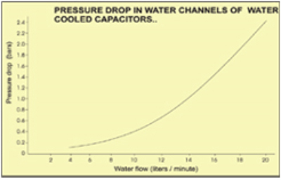
Pressure Drop in Water Channels of Water Cooled Capacitors
We strongly recommend the use of demineralized water as the cooling medium which should be chemically neutral & mechanically pure. The maximum contamination limits of the cooling water are as under.
| With Carbonate Hardness | 8°DH | 6°DH | 4°DH |
|---|---|---|---|
| PH Value | 7.8 | 8.1 | 8.3 |
| Free (Co2) | 8mg/l | 4mg/l | 3mg/l |
| Aggressive (Co2) | not allowed | ||
| Ammonia (NH3) | not allowed | ||
| Nitrides (NO2) | 0.04mg/l | ||
| Iron | 0.03mg/l | ||
| Manganese | 0.05mg/l | ||
| Sulfates | 250 mg/l | ||
| Chlorides | 150 mg/l | ||
| KMnO4 consumption | 15 mg/l |
Protection Fuses :
Fuses are not provided for medium / high frequency capacitors for Induction equipment. However line frequency capacitors of 50/60 Hz are provided with internal element fuses.
Thermal (Optional):
We offer thermal cut–off protection, which detect excessive capacitor temperature / case over–heating and trip the system in case of heating beyond preset limits‚ to prevent capacitor failure.
Over Pressure (Optional):
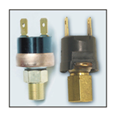
Over–pressure protection is rendered through externally mounted pressure switches to detect excessive pressure formation within the container and ensure rapid disconnection of the capacitor to prevent violent failure‚ or case rupture. (see photo alongside)
Capacitors for induction equipment applications are normally connected across the induction coil‚ which ensures rapid discharge of the residual voltage on disconnection from the supply. Therefore a separate discharge device is not provided unless specifically requested. Provision of such a discharge device protection is essential if the capacitors are switched off and re–energized at very short intervals or if the installation has an isolating switch / device connected between the capacitors and the induction coil / any other discharge paths.
Capacitors can be positioned vertically (terminal up–wards) or horizontally (terminal side–wards) and are suitable for open rack mounting or inside the furnace inverter panel. The capacitors must be installed indoors. Mounting / Fixing brackets can be provided to meet customers convenience / requirements.
Do not lift or handle capacitors by the bushing terminals / ends of the cooling–coil tubes. Before handling a capacitor unit / capacitor bank ensure that the unit is completely isolated from the supply and properly discharged‚ by repeatedly short–circuiting all its terminals with a thick insulated wire bared at both ends.
