

Low Voltage Capacitor 525V
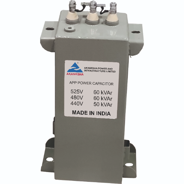
Shunt Power Capacitor
Film-foil type, oil impregnated
Application
Shunt Power Factor Correction
Technology
APP (film foil capacitor)
Material
- Dielectric: Double layer Biaxially Oriented Hazy Polypropylene (BOPP) film
- Electrode: Aluminum foil
- Impregnant: Non PCB, biodegradable oil
- Casing: Metallic, CRCA (Cold Rolled Cold Annealed)
- Case Insulation: Press phan paper
- Bushings: Polymeric
- Terminals: Brass stud with two plain washers and hex head nuts (refer drawing).
- Discharge device (external): carbon film or metal oxide film or thick film resistor
- Paint: Epoxy, light gray (shade 631 as per IS 5:2005)
Charateristics
| Application | Indoor | Insulation class (IEC60085) | 90 |
|---|---|---|---|
| Degree of protection | IP00 | Cooling | ONAN |
| Creepage Distance | 25 mm / kV | Discharge time | 3 minutes |
| Residual voltage | Less than 75 V | Temperature rise at rated voltage, frequency & room temperature | 10 ℃ (max.) container |
| IS 13585 (Part 1): 2012 / IEC 60931-1 : 1996 | |||
| Approval mark | Reference standards | Certificate |
|---|---|---|
 |
IS 13585 (Part 1): 2012 / IEC 60931-1 : 1996 | ISI Mark applicable to 440 V, 480 V and 525 V ratings |
- Element: Flat, elliptical, extended foil type
- Element connection: Soldered type
- Internal fuse: Provided
- Discharge device: Provided (external)
- Sealing: Hermetically sealed
Specifications :
| Rated output (QN) | Refer table No. 1 |
|---|---|
| Rated capacitance (CR) | |
| Rated current (IR) | |
| Rated voltage (VR) | 440 V AC |
| Rated frequency (fR) | 50 Hz |
| Capacitance tolerance | -5 / +10% |
| No. of phases and connections | Three phase, internally Δ connected |
| tan δ (dielectric) | ≤ 2 • 10-4 |
| Long duration voltages | 1.00 • VR – Continuous |
|---|---|
| 1.10 • VR – 8 hours in every 24 hours | |
| 1.15 • VR – 30 minutes in every 24 hours | |
| 1.20 • VR – 5 minutes | |
| 1.30 • VR – 1 minute | |
| Long duration currents | 2 • IR (including combined effects of harmonics, over voltages and capacitance tolerance) |
| Switching operations | 15000 per year |
| Switching current | 400 • IN |
| Life expectancy | 280000 h (at rated voltage, rated frequency & -10/D temperature category) |
| Sealing test | To check integrity of sealing |
|---|---|
| VTT | 4.3 • VR DC for 10 s |
| Discharge device test | To check capacitor discharge time after isolation of electric supply. |
| VTC | 3 kV rms for 10 s / 3.6 kV rms for 2 s of power frequency |
| C measurement | At 0.9 to 1.1 x VR between terminals |
| tan δ measurement | At 0.9 to 1.1 x VR between terminals |
| Visual | For dimensions, finish, marking |
|
Application duty |
Indoor |
|
Altitude |
2000 m (max.) above mean sea level |
|
Ambient temperature |
Category: -10/D |
|
Tmax |
+55 ºC (max. 1 hour / day) |
|
Casing Temperature |
60 ºC max. |
|
Humidity |
20% to 95% RH |
|
Degree of Pollution |
No corrosive salt, dust & sand laden. No chemical fumes, chloride gas, sulfide gas, acidic or alkaline fumes, etc. in surrounding air. No deposition of conducting particles. |
|
Seismic zone factor |
0.24 (max.) corresponding to seismic zone IV - severe 0.15g (both horizontal & vertical direction) |
|
Vibrations |
Not expected. To be installed on rigid, steady, level surface. |
| Container Dimensions | As per Drawing |
|---|---|
| Net weight | As per drawing |
| Earthing | Separate unpainted brackets provided on two sides. |
| Mounting / Lifting | Metal brackets provided on sides. |
| Mounting Position | Vertical/Horizontal Should not be mounted upside down (bushing at bottom) or in cantilever position. |
| Terminal tightening torque | M10 terminal – 6.0 to 7.0 Nm |

|
Sr. No. |
VR |
QN |
L1 |
L |
W |
H |
H2 |
Terminal |
Cable entry hole |
Mounting slot |
Approximate weight |
|
V |
kVAr |
mm |
mm |
mm |
mm |
mm |
|
Ø mm |
mm |
Kg |
|
|
1 |
525 |
10 |
394 |
340 |
115 |
150 |
150 |
M10 |
30 |
10 x 15 |
15 |
|
2 |
525 |
15 |
394 |
340 |
115 |
200 |
200 |
M10 |
30 |
10 x 15 |
18 |
|
3 |
525 |
20 |
394 |
340 |
115 |
275 |
275 |
M10 |
30 |
10 x 15 |
18 |
|
4 |
525 |
25 |
394 |
340 |
115 |
300 |
100 |
M10 |
30 |
10 x 15 |
23 |
|
5 |
525 |
30 |
394 |
340 |
115 |
350 |
100 |
M10 |
30 |
10 x 15 |
30 |
|
6 |
525 |
33 |
394 |
340 |
115 |
375 |
100 |
M10 |
30 |
10 x 15 |
30 |
|
7 |
525 |
40 |
394 |
340 |
115 |
450 |
200 |
M10 |
30 |
10 x 15 |
35 |
|
8 |
525 |
50 |
394 |
340 |
135 |
450 |
200 |
M10 |
30 |
10 x 15 |
40 |
|
9 |
525 |
60 |
394 |
340 |
135 |
525 |
200 |
M10 |
30 |
10 x 15 |
48 |