Power Factor Correction
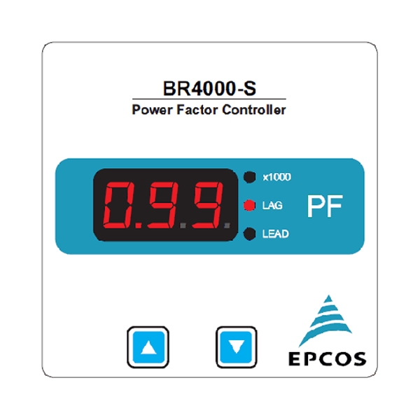
PFC BR 4000 S

Characteristics
- Intelligent control
- Minimum system setting in auto mode
- Self-optimizing control capability
- Automatic initialization
- CT ratio setting is not required
- Auto detection for number of steps
- Large voltage measuring range
- Recall function of recorded values
- Manual test mode available
- 9 Control series available
- Define direct capacitor step kvar
- Detailed expert modes
- Display of under and over compensation
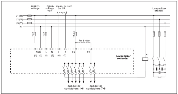
- 4 / 6 / 8 relay configuration
| Display | 3 digit 7 segment display (digit height 14mm) |
|---|---|
| System parameters displayed | Real time cos phi |
| Protection |
|
| Weight | 0.25 kg |
| Case | Panel-mounted instrument, 96 x 96 x 35 mm (back depth 55mm with add on bank module) (cut out 92+0.8 × 92+0.8 mm) |
| Ambient conditions | |
|---|---|
| Over-voltage class | III |
| Pollution degree | 2 |
| Operating temperature | 0 ... +55 °C |
| storage temperature | -20 ... +65 °C |
| Sensitivity to EMC | IEC 61326-1 : 2010 |
| Safety guidelines | IEC 61010-1 : 2010 |
| Mounting position | Flush mounting |
| Humidity class | 15% … 95% non-condensing |
| Protection class | |
| Front plate | IP50 to IEC60529 |
| Rear side | IP20 to IEC60529 |
| Operation | |
| Auxiliary supply voltage | 80 …. 300 V 50/60 Hz |
| Auxiliary supply frequency | 50Hz |
| Auxiliary VA burden(with 8 relay ON) | <8VA |
| Target cos phi | 0.8 lag. … 0.8 lead adjustable |
| Switching on and off time | 10 s fixed |
| Discharge time | 60 s fixed |
| Number of control series | 9 series preset + direct capacitor step kvar programming |
| Control modes | self-optimized intelligent control mode |
| Measurement | |
| Measurement voltage range | 80 ... 300 V AC, 240V nominal( L–N) |
| Fundamental frequency | 50Hz |
| measurement current (CT) | x/5 and x/1 Ampere possible |
| Minimum operating current | 10 mA |
| Maximum current | 6 A (sinusoidal) |
| Input current burden | <0.2VA (approx.) |
| Accuracy power factor | Current, voltage: 1% ± 2⁰ |
| Switching Outputs | |
| Relay outputs | |
| Number of outputs | 4 (without add on module), 6 ( without add on module), 8 (with add on module) |
| Switching voltage/current | Max. 250 V/ 1000W |
| Type | Voltage | Output | Alarm output | Switchover 2nd parameter set | Interface | Ordering code | |
|---|---|---|---|---|---|---|---|
| 50/60 Hz | Relay | Transistor | |||||
| BR4000-S | 240 | 4 | - | No | No | No | B44066R4104R240 |
| BR4000-S | 240 | 6 | - | No | No | No | B44066R4106R240 |
| BR4000-S | 240 | 8 | - | No | No | No | B44066R4108R240 |

- Controller hunting: - When putting the capacitor bank into operation, it is required to avoid needless switching cycles (means permanent switching on and off of steps without significant change of consumer load). This so called “controller hunting“ would increase the number of switching operations of the connected contactors and capacitors and decrease the expected life cycle (wear out) and, in worst case, capacitor bursting and fire, etc . This can be avoided by a proper programming of the BR4000S with the actual system parameters (current transformer prim. and sec., first kvar step, control series, switching time).
- Accessory for PF-Controller BR4000S
- Add on Relay module should be ordered separately.
- Please read cautions information about PFC capacitors and cautions as well as installation and maintenance instructions in the actual version of the Product Profile Power Factor Correction to ensure optimum performance and prevent products from failing, and in worst case, bursting and fire, etc.
- The actual Product Profile is available at www.tdk-electronics.tdk.com /publications. Information given in the PFC-product profile and values given in the data sheet reflect typical specifications. You are kindly requested to approve our product specifications or request our approval for your specification before ordering.
