Power Factor Correction
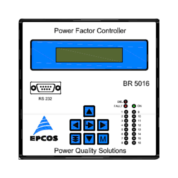
PFC BR 5016

Characteristics
- Three phase three wire measuring and controlling
- Switching relays customizable for three phase compensation
- Advance automatic synchronization features. It is Capable of giving correct results even for phase Interchange connections at CT terminals and also Wrong polarity of CTs with the help of Capacitor CT.
- Usage as power factor controller and/or as measuring device
- Intelligent control
- Menu driven handling (English language)
- 7 dedicated keys provide for modify/change the Setting and Confirm the setting by pressing the memory key.
- Programming key provide for selection the mode of operation.
- Measurement Accuracy – Class 2
- Display of harmonics (upto 15th)
- Two months of data logging. Data in the form of hourly Records & faults events records- recording all electrical values.
- 3-phase measurement of all relevant grid parameters (voltage, current, reactive power, active power, apparent power, frequency, Vthd and Ithd of each phase fundamental/RMS value.)
- Storage of values on hourly basis with date and time stamping.
- Display of date, time.
- Display of switching counter of individual banks with reset option.
- Display of harmonics upto 15th order
- LCD display 16 characters with 2 lines
- User interface English language
Modes of operation
- Auto mode of operation (normal control)
- Manual mode of operation
- Programming mode
Controlling
Simple controlling 3-phase, 3wire measurements supply. Eight switching outputs for 8steps models, sixteen switching outputs for 16step model. For 3-phase-measurement the controlling is done according to the average value of Power factor. The PF has two limit, PF upper limit and PF lower limit. The control starts when the load side PF goes below the set limit of Lower side limit.
- Over voltage/under voltage/no voltage
- Over /Under load
- Under compensated( only Indication)
- Over temperature
- C-defect
- Faults with time stamp
- NV –RAM Battery down
- Over/ under frequency
- Load unbalance
Two characters represent one of the following status of faults/ error:
| OK | Controller status is okay | LU | Load unbalance |
|---|---|---|---|
| VA | Measurement voltage is absent | OB | Out of Banks(Undercompensate) |
| OD | Outputs are disabled | OH | Over capacitor current THD |
| UC | Under capacitor current | UT | Over Internal temperature |
| OC | Over capacitor current | OT | Over internal temperature |
| NV | NV RAM Check sum error | UF | Under frequency |
| BF | Battery Fail | OF | Over frequency |
| ET | Over external temperature | UV | Under voltage |
| OV | Over voltage |
| Auxiliary voltage | 415VAC (L-L) (+20%, to -30%) |
|---|---|
| Measuring voltage | 3 phase 3 wire , 415VAC (L-L) ( +20%, -30%) |
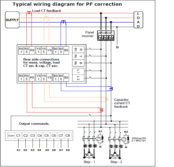
| 3 current | X:1A / X:5A selectable through the connection terminal for Load & Capacitor CT |
| PT 100 | one PT100 connection for monitor the temperature at the outside |
| Auxiliary Input | one Auxiliary input 120- 230Vac programmable for switch over 2nd target cos-phi, Reset the system faults |
- 8 / 16 relay outputs (contact NO) as switching outputs for 8 and 16 step models respectively.
- 1 independent isolated interfaces RS232
- 2 Independent isolated Auxiliary outputs potential free 5A, 230V
- 1 - independent, isolated RS232 interface ( D type nine pin connector)usage
- 1 – RS485 interface with MODBUS protocol, selectable through DIP Switch
- As interface for PC for usage with BR5000 data downloading dedicated software
| Type | BR 5000 |
|---|---|
| Operating voltage | 415 V AC(L-L) +20% to -30% , 50Hz |
| Measuring voltage(3-phase,3wire) | 415 V AC(L-L) +20% to -30% , 50Hz |
| Measuring current (3-phase) | 3 · X: 5A / X:1A selectable through connection terminals for load & capacitor CT |
| Power consumption | < 10 VA ( with max 16 relay ON) |
| Sensitivity | 200 mA / 100 mA |
| Switching outputs | |
| Relay outputs for capacitor branches | 8 / 16 relays, freely programmable for switching of 3-phase capacitors |
| Switching power of relays | 250 V AC, 1250VA/150W |
| Number of active outputs | Programmable |
| Operation and display | Illuminated LCD display 16 × 2 line |
| Menu languages | English |
| Controlling | Reach controlling of each phase (L-L) |
| Modes of operation | 3-phase: 8 / 16 three-phase capacitors |
| Control principle | Self-optimized intelligent switching mode, 4-quadrant operation |
| Automatic initialization | Possible |
| Target cos φ | 0.3 ind ... 0.3 cap adjustable |
| Correction time | Selectable from 1 sec to 600 sec |
| Discharge time | Selectable from 1 sec to 600 sec |
| Manual operation | Yes |
| Fixed steps | Programmable |
| Display/Display functions | |
| Display of grid parameters | 3- phase values cos φ, U, I, f, Q, P, S, THD-V, THD-I |
| Precision | current/voltage: 2% active, reactive, apparent power: 3% |
| Storage function | |
| Storage of faults events values | voltage, current, temperature, recorded in controller with date and time stamping |
| Storage of switching operations | each output, separately re-settable |
| Faults record events | Yes with time stamp |
| Temperature monitoring | automatic switching off of steps |
| Temperature measuring range | 0 … 70 °C |
| Interface | 1 independent isolated interfaces RS232 (with EPCOS dedicated protocol) GSM connectivity available with dedicated Modem |
| Casing | panel-mounted instrument 144(L)mm × 144(H)mm × 125(D) mm Door cutout (138mm x 138mm) |
| Weight | 2.5 kg |
| Operating ambient temperature | 0 … +65 °C |
| Protection class | Front IP: 41(with RS232 cover) IP 20(without RS232 cover) rear: IP20 |
| EMI/ EMC | IEC61000-4-2: ±8kV for Air discharge; ±4KV for contact discharge IEC61000-4-3 IEC61000-4-4: ±2kV IEC61000-4-5: ±4KV(Measurement supply); ±0.5KV( Aux. supply) IEC61000-4-6 IEC61000-4-8 |
| Type | Voltage | Measurement ( R,Y, B) | Relay Output | Interface | Ordering code |
|---|---|---|---|---|---|
| 50 Hz | |||||
| BR5000-R8 | 415V | 3 Phase, 3Wire | 8 | RS232 | B44066R5908A415N1 |
| BR5000-R16 | 415V | 3 Phase, 3Wire | 16 | RS232 | B44066R5916A415N1 |

- Controller hunting: - when putting the capacitor bank into operation, it is required to avoid needless switching cycles (means permanent switching on and off of steps without significant change of consumer load). This so called “controller hunting” would increase the number of switching operations of the connected contactors and capacitors and decrease the expected life cycle (wear out) and, in worst case, capacitor bursting and fire, etc. This can be avoided by a proper programming of the BR5000 with the actual system parameters ( current transformer primary, step kvar and correction time)
- Minimum discharge time set in the controller must be in line with the discharge device of the capacitors e.g. standard discharge resistors used by EPCOS are designed for 60 seconds discharge time. A discharge time set in BR5000 shorter than the capacitor discharge time leads to extremely high inrush current and can damage the capacitor as well as distribution equipment and may in worst case lead to capacitor bursting and fire.
- Beside high inrush currents, it has to be considered that according IEC831 standard the annual number of switching operations is limited to 5000 switching. In case of very fast switching and higher number of switching operations you are kindly request EPCOS approval for your application. For fast switching LV PFC we recommend dynamic PFC systems.
